Alternative Ignition: COPs - batch fire
Posted: Mon Apr 06, 2009 10:38 am
ON WIRING:
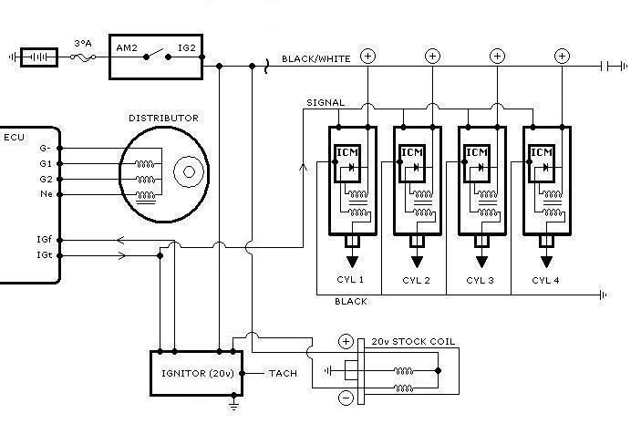
diagram re-worked in MS Paint by dr.occa from original diagrm by VitriumGTS - wiring based on 3 wire COPs from Honda Civic
------------------------------------------------------------------------------------------------------------------------------------------
"DOES IT WORK?"
------------------------------------------------------------------------------------------------------------------------------------------
"What!? No Distributor Cap!?"
------------------------------------------------------------------------------------------------------------------------------------------
"What COPs should be used?"
------------------------------------------------------------------------------------------------------------------------------------------
"SHOW ME!"

diagram re-worked in MS Paint by dr.occa from original diagrm by VitriumGTS - wiring based on 3 wire COPs from Honda Civic
Olle86 on C4AG wrote:This whole thread is very interesting... After reading it... I came across another simple solution in solving this problem. But, instead of coil packs and 4agze ignitor I'm using Coil On Plug (COP) off a Honda Civic and using original BT Harness, Dizzy, Ignitor and Coil. As Jousi mention earlier I also kept the ignitor and coil connected for tach use.
Here's What I Did.
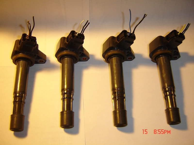
COP has 3 wires (pic above).
Black/White = Positive +
Black = Negative -
Colored/striped = Signal
1) I Connect all the negative wire (bundle) to chassis of car.
2) All positive wire (bundle) to Ignition switch 12v Blk/Orange (fire wall harness)
3) All Signal wire (bundle) connect to 20v Ignitor Yellow/Green (IGT).
4) Start your engine...
I'm no genuis or guru when it comes to electronics but just gave it a try and still shock until now that it worked. thanks to everyones infos/ideas on this "sticky thread"
I haven't had any problem yet with COP overheating, no engine light, starts & Revs smooth and nice sound, Car runs awesome.
Will post new pics of set-up later...
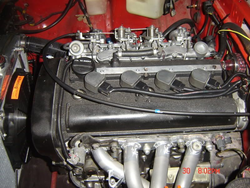
Here's an old pic of engine w/cop.
Olle86 of C4AG wrote:positive wire - black w/white (12v ignition)
negative wire - black
signal wire - brown, white, blue and yellow (connect to IGT)
not sure if civic cops wires are same color as the rsx cop's.
...Yellow w/green wire is located on igniter (igt signal).
Olle86 on C4AG wrote:on the silvertop igniter wire harness i believe it's the BLACK WIRE is your IGT signal and black/yellow is your IGF. Please correct me if i'm wrong.
Olle86 on C4AG wrote:sadtop101 on C4AG wrote:ya i know what your wire codes are, but what are the pin on the cop from left to right r cause they are hard to see in the pic that u posted. just need what each one is left to right on the cop. so it signal and then what power or neg? hard to see in pic yet again. just left to right....thanks
looking at the pics all signal wires are on left, negative in the middle and positive on the right. hope this helps... =)
VitriumGTS of C4AG wrote:SRB from C4AG wrote:Hope this isnt too noob...
But just a thought, isn't the 20v igniter a smart igniter (adds dwell to limit coil charge time at low speeds to avoid overheating the coil)
As you are bypassing the 20v igniter for the igt signal to the Honda coils, wouldn't that mean there is no dwell being added.
I assume the output from the 20v igniter is something like 12v and the COP's need a 5v signal so you cant use the igniter output for igt signal on COP's
the COPs do get a 5v signal in the form of IGt off the 20v ignitor. All 4 are tapped into a single place
check out my diagram a few posts up
VitriumGTS of C4AG wrote:SRB of C4AG wrote:Yup was looking at the diagram
The coils are tapped into the igt wire going from the ECU to the igniter
Thus the coils get the igt signal from the ECU not the igniter
Hence my question about the coils not getting any dwell added as the coils are tapped in prior to the 20v igniter (which I thought was a 'smart' igniter and added dwell)
yep. Its probably the reason why all 4 COPs can fire all at once without trouble
Olle86 on C4AG wrote: Toyota Coil on Plugs have 4 wire (POWER, IGT, IGF AND NEGATIVE). Connect everything else but the IGF (Fail safe)? - not true for 93- 1MZFE COPs. 2 wire -dr.occa
mr220v from C4AG wrote:That's one advantage to using a toyota cop. The IGF signal can be provided by one of the cops, whereas with a honda cop you still need the 20v igniter and coil for this. With toyota cops, you could eliminate the coil. That leaves the igniter there for the tach signal only.
------------------------------------------------------------------------------------------------------------------------------------------
"DOES IT WORK?"
Olle86 of C4AG wrote:I've been running the cop's since november of last year before posting anything on this topic and still going strong... no issues none what so ever...
Olle86 of C4AG wrote:mr220v of C4AG wrote:Ok, if you allowed spark to be delivered just based on igt pulse, you would get spark:
1. At the normal place, 10btc at the top of the compression stroke
2. At the bottom of the power stroke (no problem)
3. At the top of the exhaust stroke (no problem)
4. At the bottom of the intake stroke (problem)
So I'm wondering how you're not igniting your uncompressed intake charge just as it's finished entering the cylinder? Is the bottom of the intake stroke spark delivered just before the injector is fired? That's all I can think of. The 20v's injection is sequential. Maybe that intake charge doesn't include fuel until the last second? If it was batch, which includes fuel from the start, I would think the uncompressed and fueled intake charge would ignite shooting flame out the intake?
I was thinking the same way about misfirinig and flames coming out of the intake manifold like timing would be off cause I only have one signal (Igt). but, believe it or not motor idles / starts normal and smooth. C.O.P are very fast there typical charge time is around 1.8 ms. I've rev'd the motor very hard many times haven't seen anything coming out of the intake and tail pipes. Forgot to mentioned that I connect the 1 & 4 together (IGN #1) and 2 & 3 together (IGN #2) like a 4 cylinder wasted spark ignition configuration. funny thing is that I only got 1 ignition signal/pulse (IGT). 4agze ignitor should work well cause it has two Ign output.
I'll try post pics and video when I get a chance....
Hicomp4ag of C4AG located in Okinawa, Japan wrote:I totally with ya. Spend $50 or $500~$600 on a Dizzy kit... hummm
Btw, Thank you all for sharing this information ! :thumbup:
mr220v on C4AG wrote:Nope, no factory ecu will run coil packs like this. The DLI GZE uses waste spark. You would consider this even more wasteful spark as the coils are being fired 4 at a time instead of 2.
Really, this is "batch firing" your coils. The reason you can get away with this on a 20v (I think) is because the 20v is sequentially injected. So....when that intake charge is being drawn, there isn't already fuel present. The spark occurs, and then the fuel is delivered.
If this were a 16v which fires injectors in pairs, there would be fuel present when the intake valves opened for the intake stroke. With a 16v or a gze, you would backfire out your intake.
So the reason this works is the short duration spark of the honda coils, and the 20v's sequential injection.
------------------------------------------------------------------------------------------------------------------------------------------
"What!? No Distributor Cap!?"
Olle86 on C4ag wrote:ROME: yes... no cap and rotor. no issues on dirt getting in so far.
erix-7: got the c.o.p from my friend, saw Honda motor lying around inside his bodyshop. He did mention that the motor is off a civic, sorry not sure exactly what year.
Plex: the throttle response normal. it just the video quality and thanks
------------------------------------------------------------------------------------------------------------------------------------------
"What COPs should be used?"
Olle86 on C4AG wrote:most late model toyota engine with cop's will work fine. I recently tried a few like off my 06 tocama, 06 corolla and scion just before pulling the motor out of the car. they all work very well, infact they seem stronger than the Civic one's have on my motor. I'm definitley going with the 06 corolla cop's perfect size. will post pics later...
Toyota Coil on Plugs have 4 wire (POWER, IGT, IGF AND NEGATIVE). Connect everything else but the IGF (Fail safe)?.
------------------------------------------------------------------------------------------------------------------------------------------
"SHOW ME!"
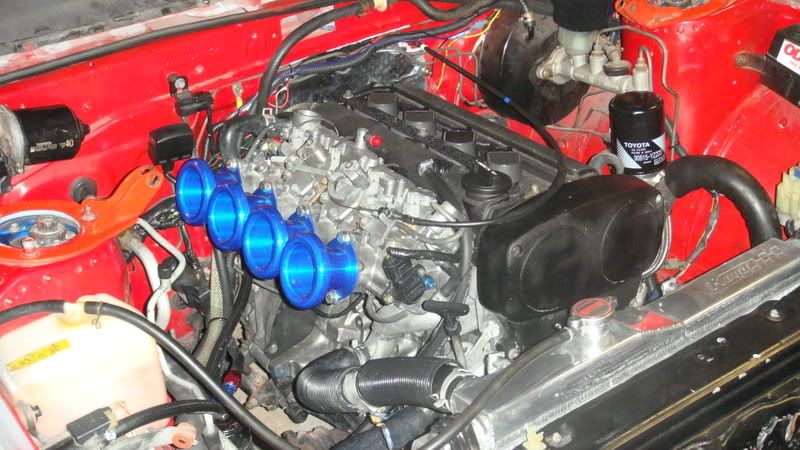
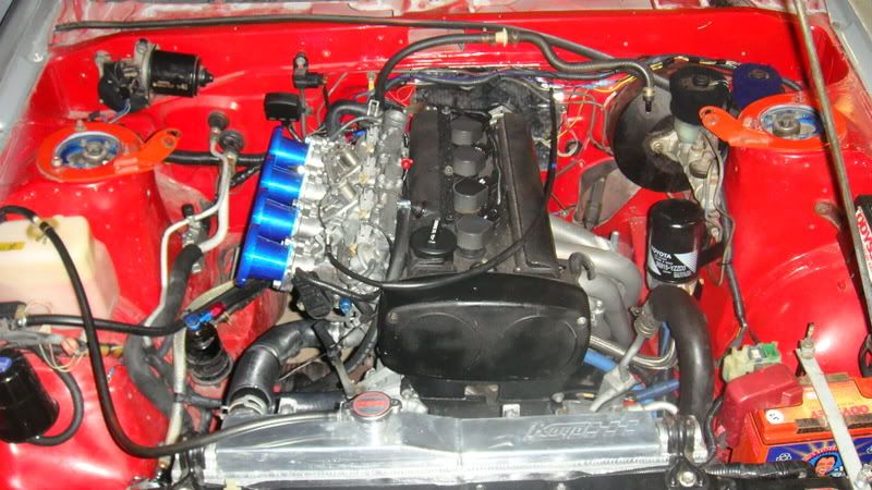
Olle86 on C4AG wrote:... here's a small kine pics & video.
video
http://s128.photobucket.com/al...1.flv
