1986 Corolla GTS 4AGE Hookup.
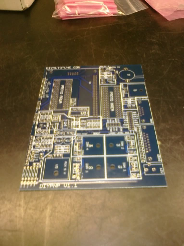
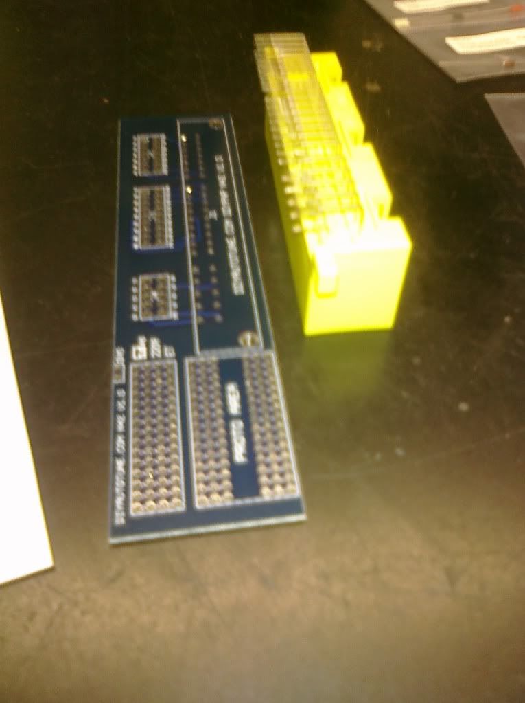
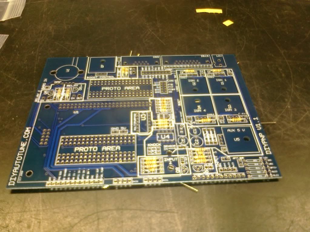
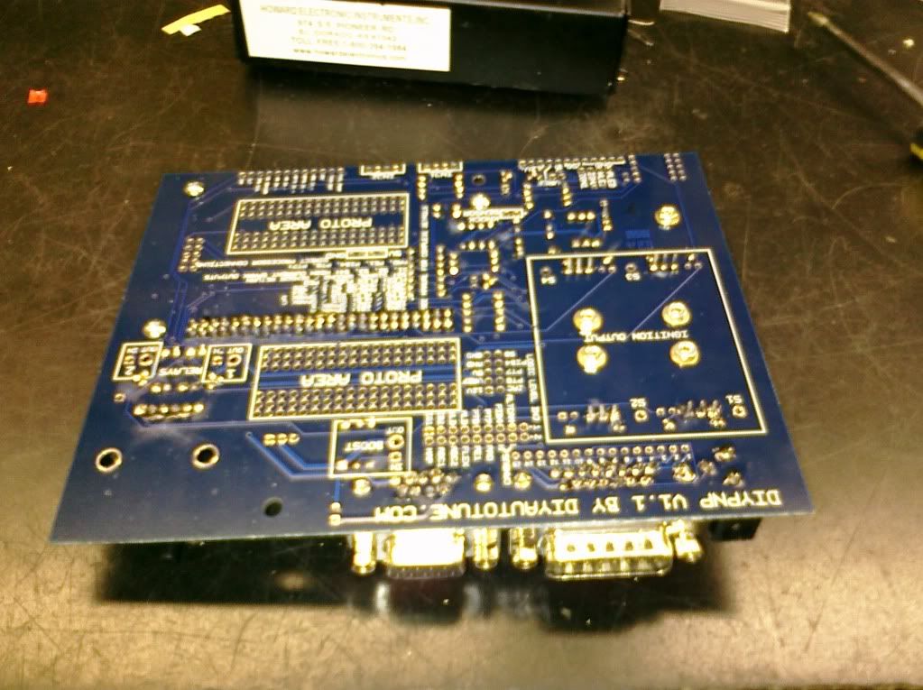
This is the main board that’s shipped with the kit. You can see everything is silkscreen labeled for easy identifications. Both sides are like this.
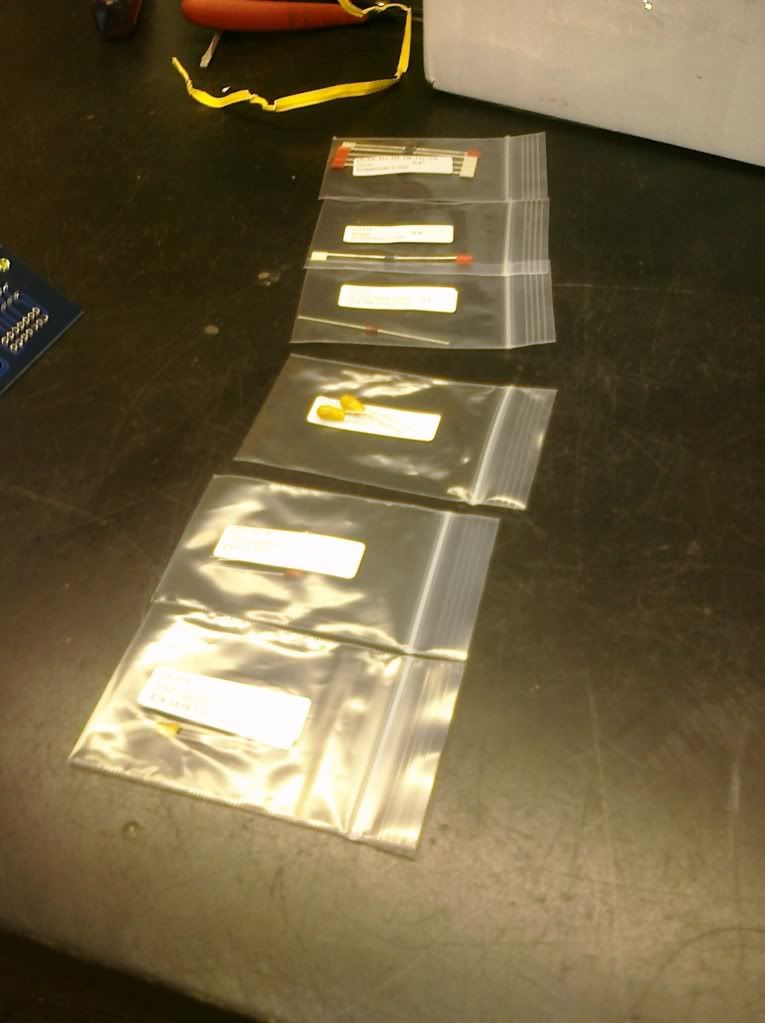
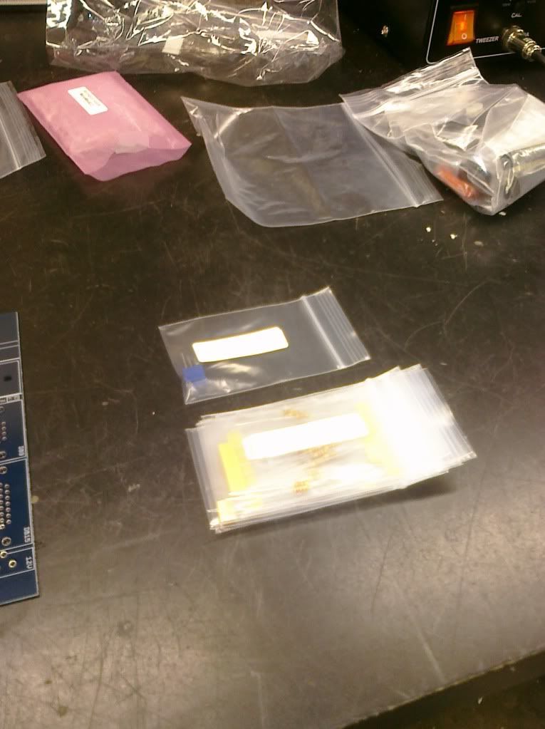
Various parts in baggies all neatly labeled!
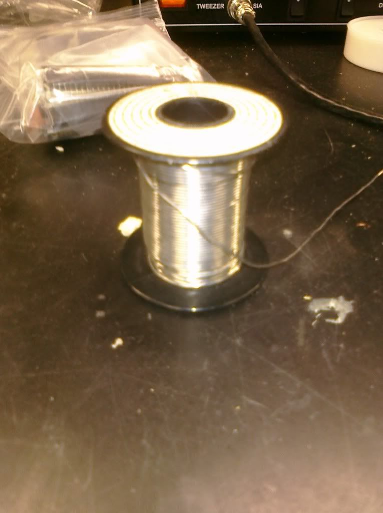
Solder! I chose the fluxed variety for easy adhesion.
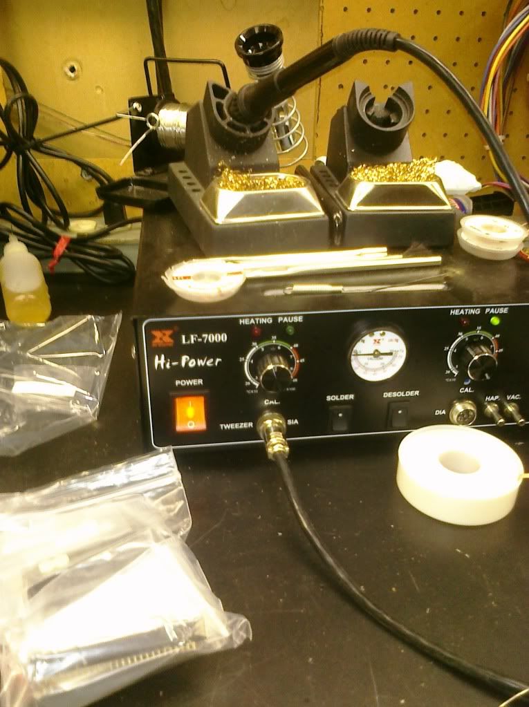
Soldering iron and sucker (if you mess anything up)
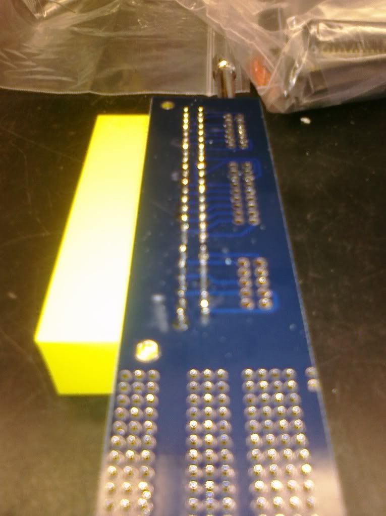
Connector board with 42 pin factory matchup connector.
I simply flipped the connector upside down and soldered away!
Started on the main board with resistor installs. I’ll get into some of the finer details later but for now these are the main labeled resistors.
Backside view, you can see I placed them all at once instead of soldering in one at a time.
 Tada! All soldered and trimmed in.
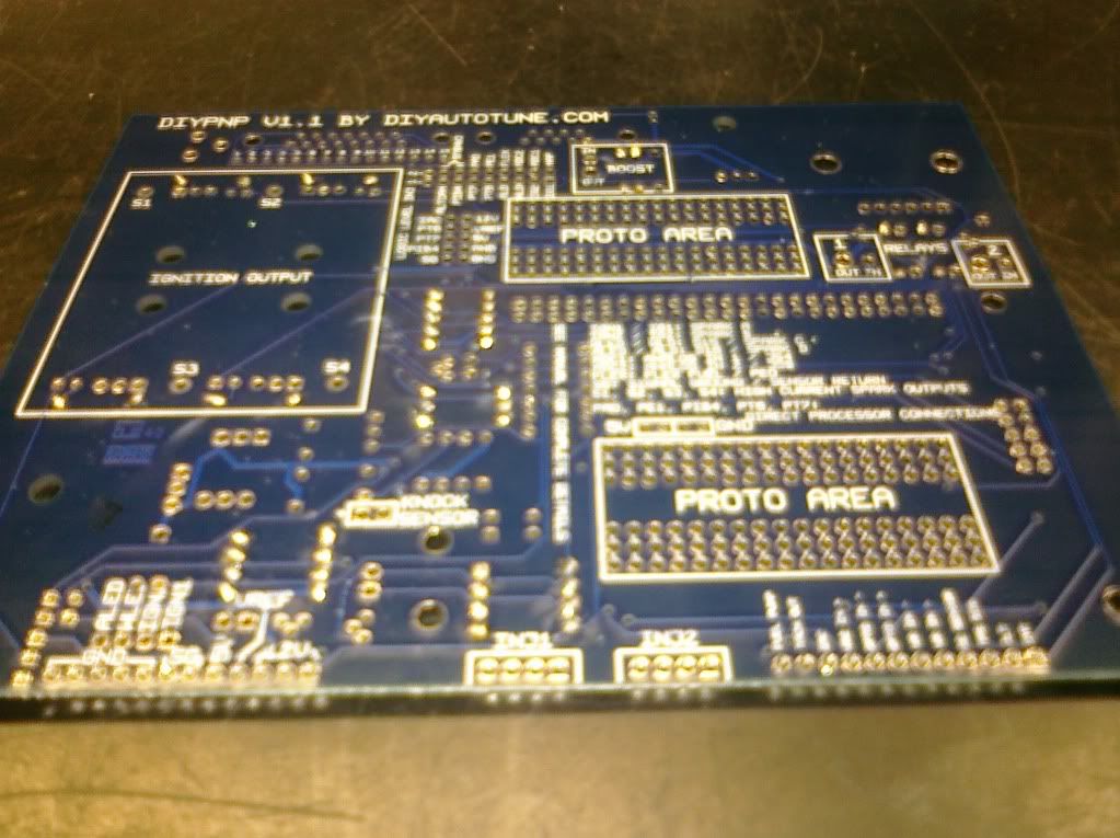
Now for the diodes.
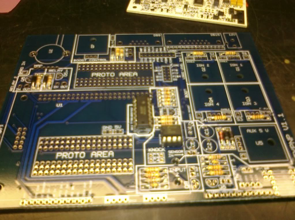
You’ll notice the IC’s in this picture have been put in sockets. These are NOT included in the kit. I chose to install them for easier changing later down the line if they needed to be.
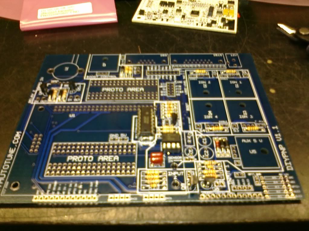
Now all capacitors, adjustable resistor box, MAP sensor and transistors are installed.
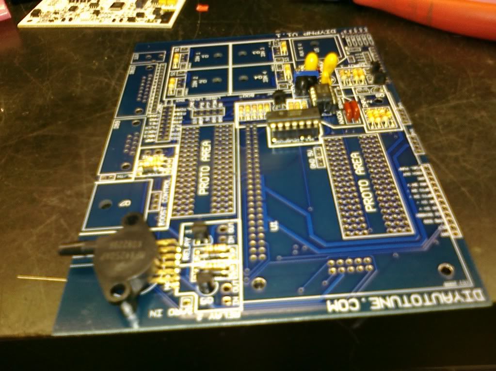
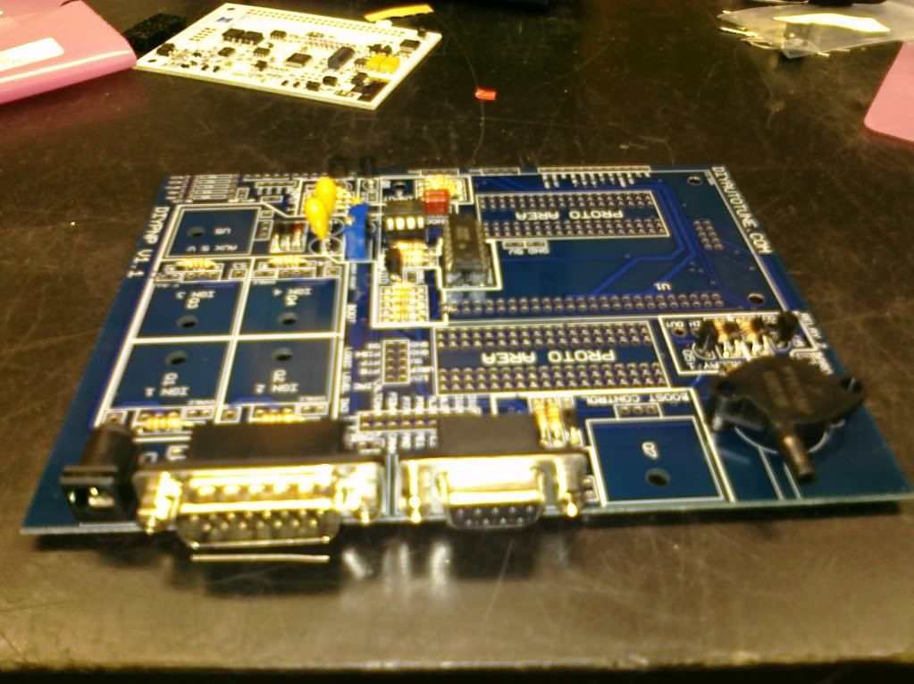
Both DB connectors and 12V connector are on now.
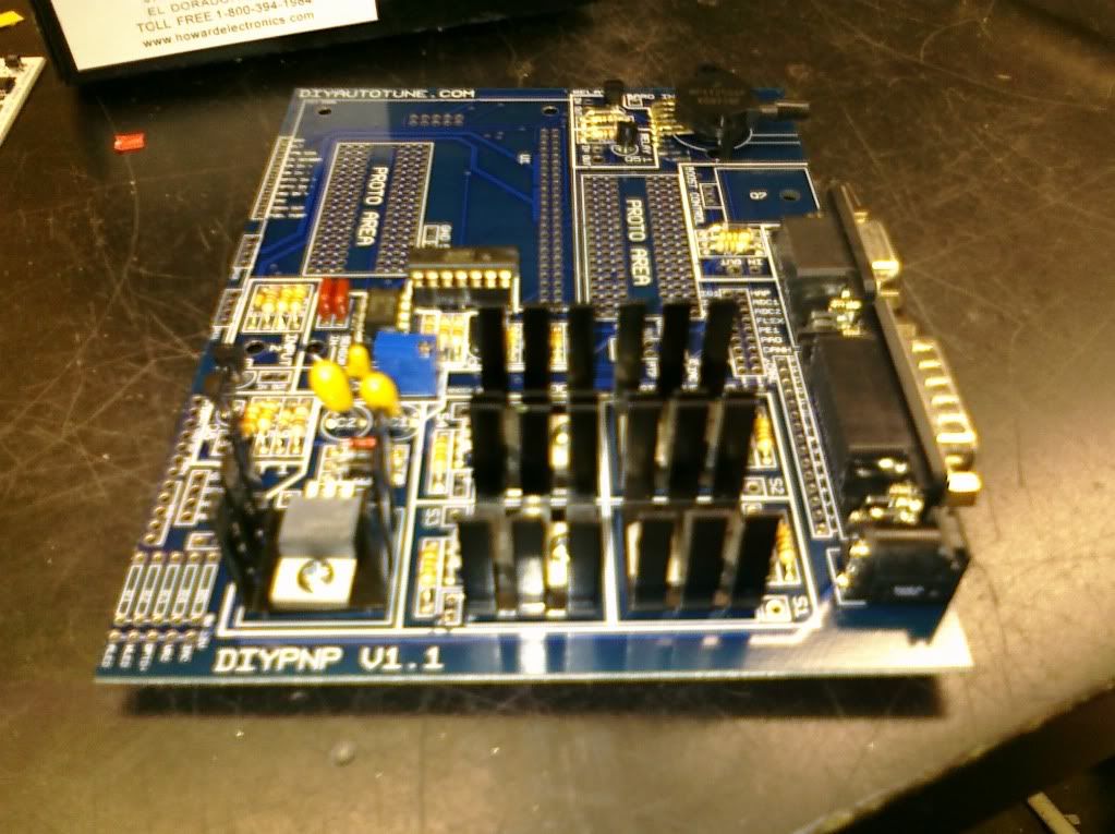
Power time! All heatsinks and ignition modules installed, boost goes on Q7 up in the corner. My application doesn’t use it, but it will be installed anyways for later functionality.
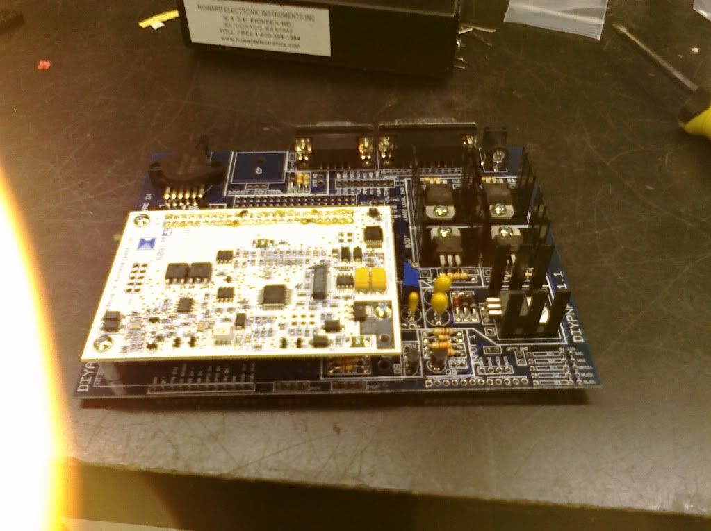
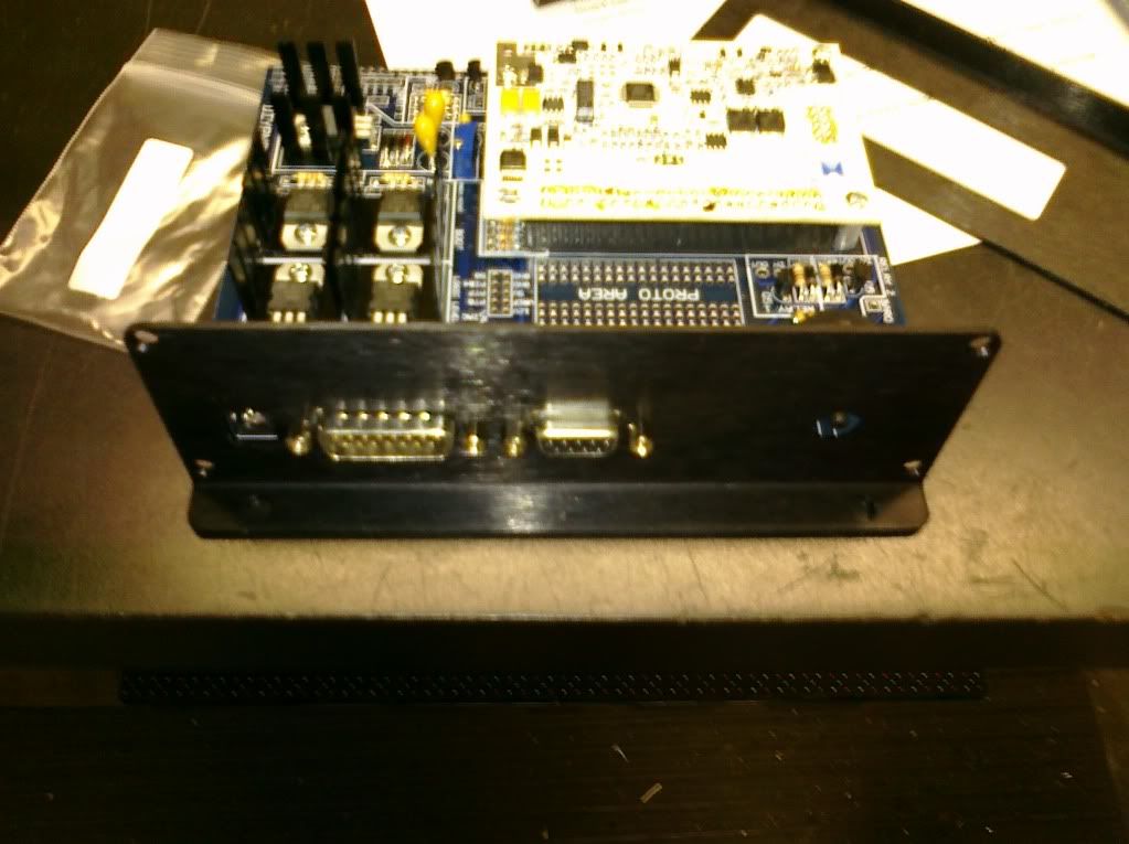
Test fitting the MS2/Extra module. Pretty straight forward, standoffs screws, two sets of connectors.
Newer bottom view.
As you can see I took off the screw down points on both of the DB connectors and attached the outside plate with them. If not the connectors sit back inside the case and are difficult to get to. I think it was designed with this in mind.
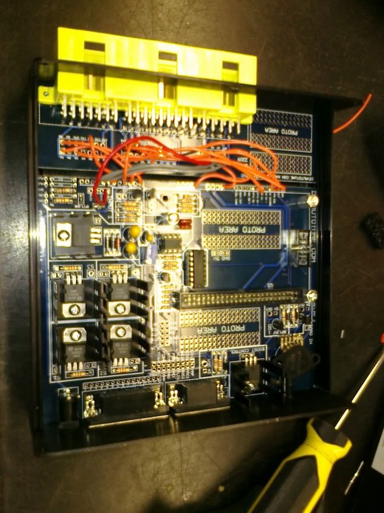
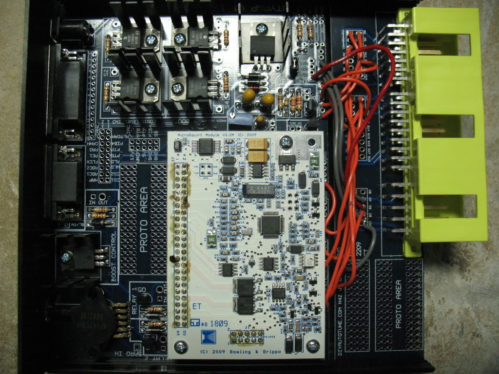
Wired in my connector board to the main unit. See the boost controller installed now?
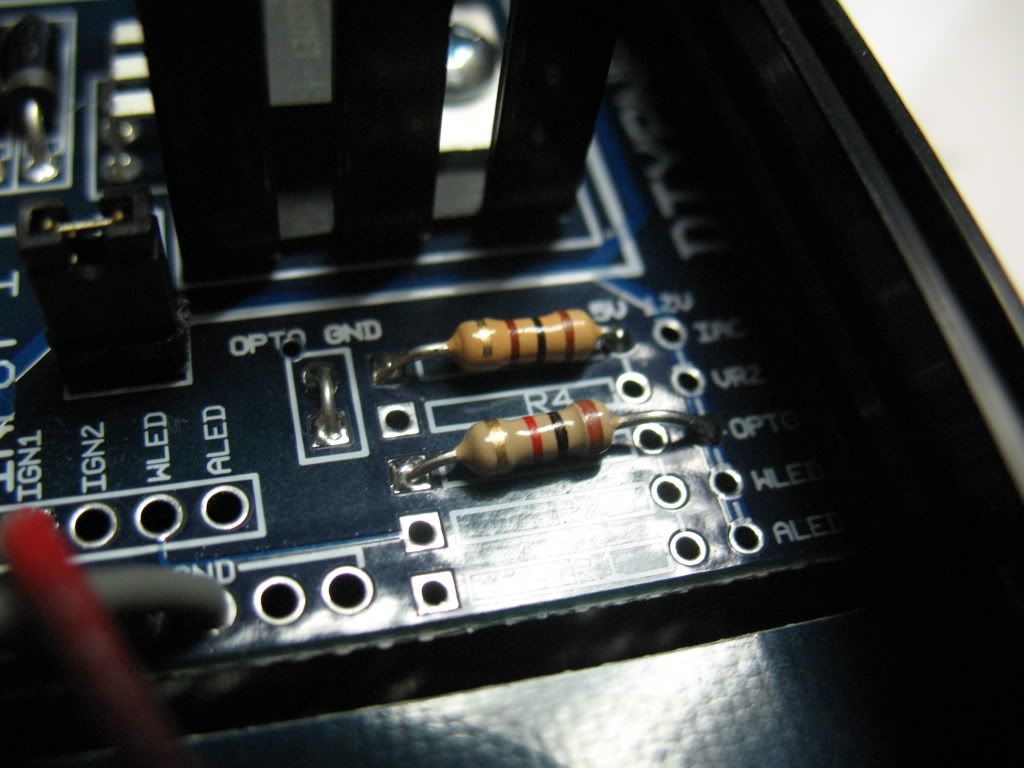
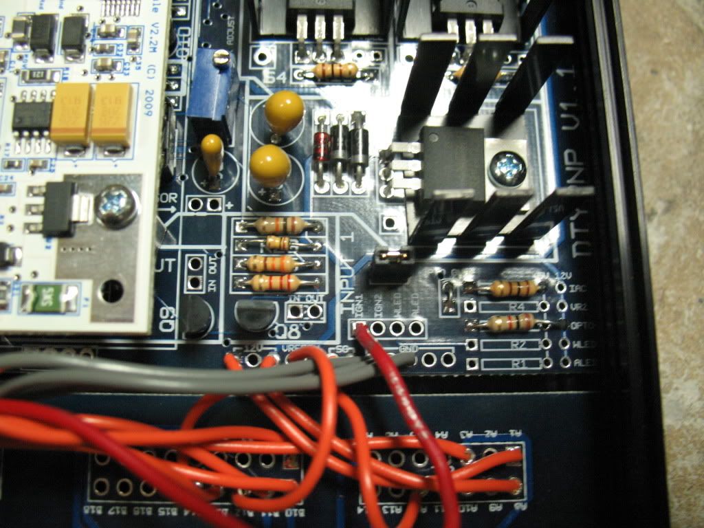
You’ll notice the two resistors in the pullup area. These must be installed for my application. Notice the OPTO+ gets a 1k ohm in the 12v hole and the IAC gets a 100 ohm in the 5v hole. Make sure the OPTO+ doesn’t touch the 5v hole as it has to pass over it.
Next step, Flashing the map!
Well, as soon as I get it finished and double checked!
More to come……..